
Damn.. That sucks, i should have read more about htis stuff before i got it going. Im always like that, i want it to happen right now, not later.
Anyway, i could probably change the electronics later on.
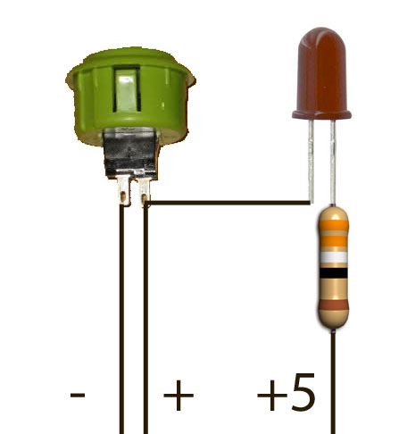
For a normal LED blink when the button is pressed, how should it be wired you guys think since it's 9 poles on the switch.

Results 11 to 19 of 19
-
06-02-2011, 12:34 PM #11Tech Convert

- Join Date
- Jun 2011
- Posts
- 16

-
06-02-2011, 12:55 PM #12Tech Guru

- Join Date
- Mar 2011
- Location
- UK, Ukraine, Romania
- Posts
- 2,836
not sure about your buttons but this is how fbonito wired up the arcade buttons for his gamepad based awesome diy arcade controller:
i really have no clue why there's 9 poles on your buttons...11mba / 13mbp / tsp2 / live9 / audio10 / 2x reloop rp7000gold / 2x xdj1000 / 2x d2maschine mk2 / x1 mk2 / z1 / f1 / midifighter / lpd8 / 2x launchpad / launchkontrol xl
 Originally Posted by derschaich
-
06-02-2011, 01:46 PM #13Tech Convert
- Join Date
- Jun 2011
- Posts
- 16
Will try that LED scheme when i get the switches combined with another i found on the net.
I fixed the box now atleast and made it black, not by spraypaint but by wrapping it in vinyl, i work at a signshop and is used to doin cardecor and shit so.
And most important, it was free

-
06-02-2011, 03:03 PM #14Tech Mentor
- Join Date
- Aug 2010
- Posts
- 496
I think that vinyl's gonna be fucked when you start drilling holes in the box. Lucky it's free I suppose? Originally Posted by rudeez

-
06-02-2011, 03:04 PM #15Tech Guru
- Join Date
- Mar 2011
- Location
- UK, Ukraine, Romania
- Posts
- 2,836
good point... probably better to drill the holes first... Originally Posted by Tha Gooch
11mba / 13mbp / tsp2 / live9 / audio10 / 2x reloop rp7000gold / 2x xdj1000 / 2x d2maschine mk2 / x1 mk2 / z1 / f1 / midifighter / lpd8 / 2x launchpad / launchkontrol xl
Originally Posted by derschaich
-
06-02-2011, 03:19 PM #16Tech Convert
- Join Date
- Jun 2011
- Posts
- 16
Haha, jeah i know but i gonna make a "brushed aluminium" look decal just a bit smaller with rounded corners on top of it and print the name of it aswell as namnes above the buttons and knobs. gonna carv the vinyl away before i drill the holes so that's fine, i just wanted to do something in the meantime while waiting on the buttons!
EDIT: Is it possible to do dimmer leds to the 10k pots?
-
06-02-2011, 06:15 PM #17Tech Guru

- Join Date
- May 2009
- Location
- Scotland
- Posts
- 686
EDIT: Is it possible to do dimmer leds to the 10k pots?
Yes, connect the variable connection (often known as the wiper) to the positive leg of the led, and connect the negative leg of the led to ground. This should light up the led when at full, keep it dim at around half and off when in the off position.
-
06-03-2011, 01:03 AM #18Tech Guru

- Join Date
- Oct 2008
- Location
- Cincinnati, OH
- Posts
- 1,158
For the foot pedal/pots, you could use something like this...
http://backstage.musiciansfriend.com...50360000000000

And just wire up one of your analog inputs from the gamepad to a TRS jack on the side of your box.
The pedal is just a pot on the inside, so if it's the wrong resistance you could just open it up and change the pot.
And to setup the LEDs to stay on when you press a button on your pedal, you could wire up a relay like one of these...
http://www.sparkfun.com/products/524
to each button and each LED.
The relays would act as on off switches.
You might have to power the led's with a battery rather than the board though.
-
06-04-2011, 09:20 AM #19Tech Convert
- Join Date
- Jun 2011
- Posts
- 16
So, im currently working on the knobs while waiting for the switches to arrive.
I've hooked up 10k linear pots to both X and Y axis.
They're working great and except one thing.
It dosen't react until iv'e turned it to about 11 o clock.
And the other one reaches maximum at about 2 o clock.
Does that have to do with calibrating the gamepad or is it wrong ohms on the pots?
Also, how and where do i hook up a led to them to get them to act as dimmers?
EDIT: I noticed something about Arduino UNO, would that work for my project and all the things i wanna be able to do with leds etc?

Last edited by rudeez; 06-04-2011 at 12:10 PM.

 Reply With Quote
 Posting Permissions
|
|
© 2023 DJTechTools
Bookmarks