
Good question. Im currently using the pervious mega board so use a program called sterial to usb to get midi over the usb connection. The new mega boards have the ability to be reprogrammed as a midi device.Originally Posted by safefire


Results 11 to 20 of 28
-
03-24-2011, 08:34 AM #11Tech Wizard

- Join Date
- Nov 2010
- Posts
- 33

-
03-24-2011, 03:35 PM #12Tech Mentor
- Join Date
- Feb 2011
- Location
- Southern Ontario, Canada
- Posts
- 244
There are three (well, four, but one is not suitable) ways of doing midi from an arduino.
One method uses the hardware serial ports available on the atmega chips (1 on the uno/etc, 4 on the mega) to send midi messages directly to whatever midi device you want. (usb->midi, midi thru box, midi keyboard, you name it... it's freakin midi! )
)
Another method would be to use a standalone usb->midi device, hack it apart, connect things and install it into your case... BAM! instant usb midi... (note that you will still use the previous method to send the midi--direct thru the hardware serial port, it's just directly connected to the midi->usb converter).
The third method can only be used on the newest arduino boards, uno's for sure, not 100% sure about the mega's (the ones that use a dedicated atmega8 chip as the usb->serial converter instead of the regular FTDI chip). Since they use a dedicated microcontroller, you are able to reprogram it for your own purposes. Someone has already made a port of LUFA that will work on these new arduino's.. I don't have a link right now, but a quick google 'arduino uno lufa' should bring it up.
The fourth (and not suitable) method is what you're using right now, which is a client running on your computer to translate the serial messages into midi messages. This adds SIGNIFICANT latency, to the point of being useful for debugging only, not for performance.
Feel free to ask more questions... I have some work stuff going on at the moment, but when I get a chance I can post working midi-in and midi-out schematics.
Midi-out is nothing but a pullup resistor and the correct wiring.
Midi-in is a little more complicated, as you need an optoisolator to convert the rs232 midi signal to a TTL signal for the arduino.
It CAN be done My current setup consists of three homebrew midi controllers (one of them is still on a breadboard) all with midi-in and out, with the code performing midi-thru functions to daisy chain them. They're all connected to a single m-audio uno midi->usb converter. They work flawlessly... ZERO latency... One of them has a bunch of leds responding to midi-in FROM traktor, one set (of eleven) is the crossfader position, and I have two more that flash in time with the beats (one per deck).
I will be posting something regarding that one, since it is the more complex of the two (I hacked the MF source into my controller so I could emulate the MF's 4 banks mode. Allowing me to use the instant gratification mapping. In addition to providing me a complete dual deck transport section.
-
03-24-2011, 03:51 PM #13Tech Guru

- Join Date
- May 2009
- Location
- Brighton / Bangkok
- Posts
- 1,386
can't wait!
is midi in difficult no matter which of the 4 options you choose?
someone needs to sell a pre-programmed arduino that comes with everything you need to get midi up and running with little-to-no programming needed... (hint hint!)
-
03-24-2011, 04:44 PM #14Tech Mentor
- Join Date
- Feb 2011
- Location
- Southern Ontario, Canada
- Posts
- 244
Yep, midi-in can be a PITA if you don't know what you're doing going into it... There are LOADS of bad schematics out there, with a few good ones thrown in to confuse us.
The toughest part I found (having not much real electronics knowledge -- i'm all self taught) was finding a suitable optoisolator (optocoupler is another term). Without getting technical, they physically and electrically isolate two circuits from each other.
Standard rs232 serial is usually around +/- 10v (+10v being logical 1, -10v being logical 0), remember that MIDI is nothing but normal serial data running at 31,500bps. So if you were to plug the midi-out (or is it in? the direction naming scheme for midi is mighty confusing) FROM a midi device into the midi in on your arduino, you would be able to see the magic smoke that makes electronics work (in other words, you'd likely fry your chip).
Therefore you need a way to convert the rs232 serial into TTL serial which is simply 5v (5v for logic 1, 0v for logic 0... Cake!), normally the on-board FTDI usb->serial converter will handle this for you (and does when you're programming the board), so if you want to directly connect incoming serial (midi IS serial) to the arduino, you gotta do things yourself
Enter Optoisolators! They are a very very simple IC that consists of an infrared LED emitter, and a photo-transistor as a detector. The rs232 connects to the led side, and the transistor connects to your micro-controller. This means that the only 'connection' is the light path between the emitter and detector.
This is also where the problems are encountered... In order for the serial data to be valid timing is VITAL and the input/output timings of the IC is very important, too slow to turn on and it you will have problems, too slow to turn off, again... problems... Once you get the right chip (there's a bunch that will work fine) along with the right resistors (these are the root cause of issues, incorrect resistors and, yep! Problems...) everything is hunky dory... but with a ton of bad information out there it can be a little daunting to the novice (myself included).
Right now I have used 4n35's and find them to work just fine.. I have recently picked up a bunch of PC900v's which are the IC's stated in the official MIDI spec, but I have yet to try them out.
Sorry for the wall of text, but it's a fairly complex topic especially if you want to understand the why behind things...
-
03-24-2011, 06:40 PM #15Tech Guru
- Join Date
- May 2009
- Location
- Brighton / Bangkok
- Posts
- 1,386
I think I'm just gonna end up using my Arduino for midi out in that case! All I really need it for is a bunch of pots (via a mux) and some digital buttons. The encoders and LEDS are being dealt with by a Highly Liquid CPU which has no problem dealing with midi in (obviously!).
btw - I just replied to your pm
-
03-24-2011, 07:20 PM #16Tech Mentor
- Join Date
- Feb 2011
- Location
- Southern Ontario, Canada
- Posts
- 244
nah man... it's not thaat tough.. once you get the circuit working, the rest is cake.... though not processing midi-in does leave the arduino more time for other stuff...
-
03-30-2011, 08:40 PM #17Tech Wizard
- Join Date
- Nov 2010
- Posts
- 33
So adding a 16pin mux chip onto this design is going to require increasing the board size=more expensive to manufacture. So I have instead broken out some pins so I could easily make a very small breakout board that could be plugged in the bottom. Here is a picture.
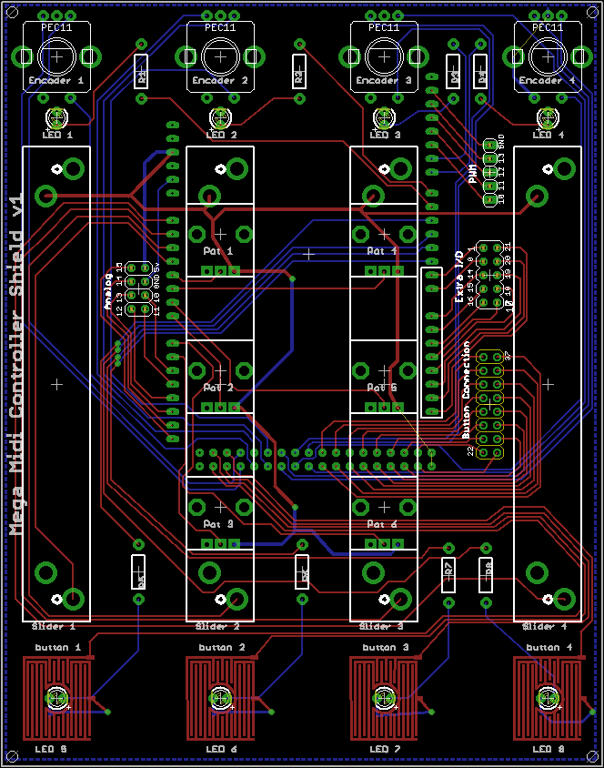
As for midi in/out I would consider ordering a bunch of Atmega8U2 and programming them with the MocoLUFA firmware. However, the end user would have to desolder thier chip and solder on a header to allow swapping of the chips (which would actually be great reprogramming via usb). But would it just be easy to get an ICSP cable if you want to change the firmware in the future? Let me know what you think, thanks!
-
03-30-2011, 11:28 PM #18Tech Guru

- Join Date
- Aug 2010
- Posts
- 623
anything that involves not alot of soldering Originally Posted by bobsagat666
Setup: VAI-40, Nanokey2, APC20, Ableton, (Shit ton of VST), TP2, DN SC2000, LPD8 (RIP) MF3D (with custom Mapping FX for ableton for Turnado and Artillary2 (ill release it when its been perfected.) PM me if interested in the mapping or helping me with it. Originally Posted by ctrld
-
03-31-2011, 01:36 PM #19Tech Mentor
- Join Date
- Jun 2010
- Posts
- 171
This is brilliant. And $30? Sh*t yeah.
-
04-01-2011, 09:49 PM #20Tech Mentor

- Join Date
- Nov 2009
- Location
- The land of the leprechaun
- Posts
- 456
@DJnecro where did you obtain this wealth of Arduino knowledge?? The reason i ask is because im in first year electronics in college and we are learning Picaxe which is so uninteresting and id prefer to direct myself towards gaining some sort of knowledge of Arduino which i could actually use.
ThanksI play everything Indie/ Rock/ HipHop/ Cheese/ Electro/ Dubstep and anything that sounds good
Tsp 1.7/ Tsp 2/ Sony vaio Win 7 4gb Ram / Macbook Pro 13 inch (Main machine) /vci 100 se/ mixdeck/ audio 8/ technics rph headphones/ Custom xBox Controller/ Akai Lpd8

 Reply With Quote
 Posting Permissions
|
|
© 2023 DJTechTools
Bookmarks