
PART ONE: The Basics
In this guide I'll try to guide the inexperienced solder through the making of a connection panel for your dj-setup. All links for shops will be to Thomann.de, they ship to most of Europe. If you're in the US, try to google the product number.
Why would you want to make a connection panel?
Well first of all it looks good and professional, and second it makes setting up at your gig so much easier.
Where can i use it?
The connections panel I've used is a 19" rack standard. That means it will also fit in any 19" amp racks. My flightcase came with a 19" 1 unit slot, for this exact purpose.
What do I need?
A standard 19" connection plate comes with 12 holes in D size. You can get the with fewer. You can mix how the connecters how you want, but ill write this guide to the exact panel i made.
For that you need:
1x 19" connection panel (http://goo.gl/Sv4fU)
2x XLR sockets, male (http://goo.gl/UBwFo) - Main out
2x XLR sockets, female (http://goo.gl/ok9oe) - MIC inputs
2x Standard XLR cables, male-female (http://goo.gl/LSdWK)
2x RCA sockets, red, female (http://goo.gl/ugBUI) - Extra channels in/out
2x RCA sockets, white, female (http://goo.gl/kjwQ5) - Extra channels in/out
1x Standard RCA cable, male-male (http://goo.gl/vpHjN) - Extra channels in/out
2x USB sockets (http://goo.gl/H2IBx) - USB in/out for soundcard, MIDI, etc.
1x PowerCon socket, in (http://goo.gl/xxJDY) - Power in
1x PowerCon plug, in (http://goo.gl/marXT) - Power in
2x Standard power plug (whatever is used in your country) - Power in
1x Standard extension cord (whatever is used in your country, but something like this: http://goo.gl/vC2D3) - Power in
1x PowerCon socket, out (http://goo.gl/S6QmH) - Power out
1x PowerCon plug, out (http://goo.gl/JV3fO) - Power out
1x Standard (single) power socket (whatever is used in your country) - Power out
1x Standard household extentioncord - Power in/out
Solder
Soldering iron
Tape or strips
A couple of hours
Well, that was a lot of information. But its not that difficult, let me break it down with a picture.
Connection panel (from left to right)
- PowerCon - In
- PowerCon - Out
- Mic 1
- Mic 2
- USB - In
- USB - Out
- RCA 1 - Left
- RCA 1 - Right
- RCA 2 - Left
- RCA 2 - Right
- Main Out - Left
- Main Out - Right
But what about all the extension cords and cables?
Well, you're going to fabricate your own cables for power in and power out. This (proberly) won't demand any soldering. Its pretty easy, just remove the isolation and disassemble the plugs and sockets and mount the cords. The sockets have illustrated where positive, negative and ground goes.
But what about on the other side of the panel?Code:<Standard Plug>--------CORD-------<PowerCon In Plug> <PowerCon Out Plug>---------CORD-------<Standard (single) Socket>
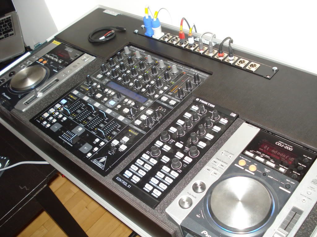
In the top left of this picture, you'll see the 'power-area' of my flightcase. The 2 first sockets is for power in/out. Lets start with the power, and all the audio will be explained later on.
You simple just cut the plug of the extension cord, because the end of the cord is going to be soldered to the PowerCon In socket. Just like the PowerIn the cord for power out is going to be soldered to the PowerCon Out socket. I will return on all the soldering later. Right now its just explaining. When you but you extension cord, remember to buy one with enough sockets, and remember that one socket is used for power out.Code:<PowerCon In Socket>-----EXTENSION CORD-<Socket><Socket><Socket><Socket> <PowerCon Out Socket>-----CORD-----<Standard Plug>
Lets carrie on to the MIC sockets. My mixer supports 2 mics, therefore there is 2 MIC socket. These 2 socket are identical. The cables will look like this:
The next 2 sockets is the USB in/out. On the first picture its 2 USB out, but since i've built in a USB hub in my flightcase i've changes one of them to USB in. No soldering here. The USB socket are flipable between USB Type A (The one that goes in to your computer) and USB Type B (The one that goes in to a printer, MIDI fighter etc).Code:<XLR Female Socket>-----XLR Cable-----<XLR Male Plug>
The next 4 socket are RCA for extra sound in or out. They are all identical, but for the ease use the same colors on the cable to the same color in the socket. The cable will look like this:
The last 2 sockets are for my main out. Most mixers have XLR out, few only have RCA as main out. It is possible to make RCA to XLR if you would like to have XLR sockets as out. The Main Out is made just like the Mic cable, but opposite.Code:<RCA Female Socket>----RCA Cable-----<RCA Plug Male>
PART TWO is already here! Right in this thread!Code:<XLR Male Socket>-----XLR Cable-----<XLR Plug Female Plug>
Please feel free to come with feedback, questions or spelling corrections.

Results 1 to 7 of 7
-
05-19-2011, 03:37 PM #1Tech Wizard


- Join Date
- Jan 2011
- Location
- Copenhagen, Denmark
- Posts
- 20
 How to make for 19" connection panel!
Last edited by brammer; 05-19-2011 at 05:56 PM.
KONTROL S4 MK1 | KONTROL F1 | KONTROL X1 MK1 | TRAKTOR SCRATCH PRO 2 | AUDIO4DJ | MACBOOK PRO 13"
-
05-19-2011, 04:31 PM #2Tech Mentor

- Join Date
- Feb 2011
- Location
- Bristol, UK
- Posts
- 210
You are one fast worker!!!


-
05-19-2011, 04:45 PM #3Tech Wizard
- Join Date
- Jan 2011
- Location
- Copenhagen, Denmark
- Posts
- 20
I can't let the people wait, can I? Originally Posted by Buffalo Ill
 KONTROL S4 MK1 | KONTROL F1 | KONTROL X1 MK1 | TRAKTOR SCRATCH PRO 2 | AUDIO4DJ | MACBOOK PRO 13"
-
05-19-2011, 05:57 PM #4Tech Wizard
- Join Date
- Jan 2011
- Location
- Copenhagen, Denmark
- Posts
- 20
PART TWO: The Soldering
PART TWO: The Soldering
Now for the fun part, the soldering. Make sure to have your solder, a nice hot soldering iron and a good place to work (i made mine at my coffee table, and it made it all a bit harder). The solderings is the crucial part. There's not much to fuck up in the soldering of the power sockets, but if you do a bad or 'cold' soldering of the audio cables, it will result in static noise.
With that in mind, it's important to make sure that the different metal parts of the socket isn't soldered together. But don't worry, you will soon enough see how your soldering skills are.
The Power Sockets
Both PowerCon sockets are made of plastic, so make sure you don't melt it with the soldering iron. There are 3 connectors in the PowerCon sockets: postive (+), negative (-) and ground (the symbol is a upside down T). In most european countries isn't any differens between positive and negativ. In the US there is a difference. It dosen't matter which wire in the cord you use, as long as its the same wire for positive in both ends, and same wire for negative in both ends (FOR US ONLY). Its important that the ground wire is the same in both ends (ALL REGIONS). If your cord only has 2 wires inside its positive and negative (not ground).
Make sure to solder the end of every wire, before soldering them to the socket.
IMPORTANT: Put the cord from your Power In through one of the holes in your panel and the cord from your Power Out though another hole! You won't be able to get them through after the soldering.
It's recommended to use a cord with ground (I'm not too familiar with the US power grid, and how common ground is 'over there').
The XLR Sockets (MIC & Main Out)
Now for the audio part, and this is where it gets more tricky. For starters a little disclaimer: My guide is based on that your Mic input is a XLR socket. Some mixers and controllers use a balanced jack for Mic input. I'll cover this briefly at last.
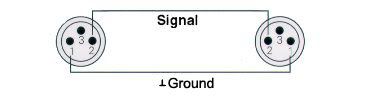
Speaker cable (XLR):
MIC cable - Balanced (XLR):
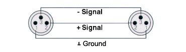
Theres no difference in soldering MIC cables and speaker cables, this is just to illustrate the signal going through the pins in the XLR. So make sure that PIN1 is connected to PIN1, PIN2 is connected to PIN2 and PIN3 i connected to PIN3.
As you can read in PART ONE, maybe you already bought 2 standard XLR cables. Now take both of them and cut them in half on the middle. You could make you own XLR cable, just as the power cables, but this is much easier.
Now take the ends with the female plug and remove the first layer of isolation. Now solder the end of every wire, before soldering them to the socket.
Inside the cable is 4 wires. 1 postive, 1 negative, 1 ground and 1 for the casing. When you look at the back of the socket, you'll see 4 connectors. At the plug in the one end of the cable, you see the numbers 1,2 and 3 to the respective pins. Open the plug (GENTLE) and se which wires goes to which pin, and now solder the respective wires to the respective connectors on the socket (you'll see the numbers right next to the connectors).
Make sure the soldering is made properly and it don't fall of when you move the cable around (GENTLE, don't pull).
Now repeat this for both the Mic XLR and the Main Out XLR.
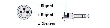
If your mixer/controller got a jack input for Mic, just get a Jack stereo-Jack stereo cable, and do it the same way. Use this picture to guide you to which wires goes where.
The USB Sockets
No soldering here! Weeee ^_^! Just flip the socket the way you want it.
The RCA Sockets (Additional In/Out)
The soldering of the RCA cables is much easier than the XLR cable.
I couldn't find a illustration for a RCA plug, but it's exactly the same as a regular jack cable.
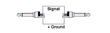
Now take the RCA and pull the stereo cable from each other! Now you have 2 mono RCA cables. Now cut these 2 cable on the middle, and remove some of the first layer of isolation. Now you'll see a bunch of cobber strings, pull them to the side and twist and solder them together. The cobber strings (the ground) was hiding another layer of isolation. Remove the isolation, and twist and solder the cobber string that appears now (the signal). The outer cobber goes to the outer connecter on the socket, and the middle cobber goes to the center connector on the socket.
Repeat this 3 more times.
If you done everything right you should now have:
More to come!Code:1x <Standard Plug>--------CORD-------<PowerCon In Plug> 1x <PowerCon Out Plug>---------CORD-------<Standard (single) Socket> 1x <PowerCon In Socket>-----EXTENSION CORD-<Socket><Socket><Socket><Socket> (Through a hole in the 19" panel) 1x <PowerCon Out Socket>-----CORD-----<Standard Plug> (Through a hole in the 19" panel) 2x <XLR Female Socket>-----XLR Cable-----<XLR Male Plug> 2x <XLR Male Socket>-----XLR Cable-----<XLR Plug Female Plug> 2x <RCA Female Socket, Red>----RCA Cable-----<RCA Plug Male, Red> 2x <RCA Female Socket, White>----RCA Cable-----<RCA Plug Male, White> 2 USB Sockets
Please feel free to come with feedback, questions or spelling corrections.
Last edited by brammer; 05-19-2011 at 06:06 PM.
KONTROL S4 MK1 | KONTROL F1 | KONTROL X1 MK1 | TRAKTOR SCRATCH PRO 2 | AUDIO4DJ | MACBOOK PRO 13"
-
05-19-2011, 07:03 PM #5Tech Mentor

- Join Date
- May 2010
- Location
- Sheffield - UK
- Posts
- 255
Nice tutorial and very detailed - thanks
-
05-19-2011, 07:16 PM #6Tech Wizard
- Join Date
- Jan 2011
- Location
- Copenhagen, Denmark
- Posts
- 20
Thanks alot! I'm glad you find it useful!
PART THREE is still coming up, about the installation and mounting!KONTROL S4 MK1 | KONTROL F1 | KONTROL X1 MK1 | TRAKTOR SCRATCH PRO 2 | AUDIO4DJ | MACBOOK PRO 13"
-
05-20-2011, 06:39 AM #7Tech Mentor

- Join Date
- Aug 2010
- Posts
- 259
Damn man, you work fast!
Good work, it looks like (I should really get my ass together and read it through, instead of just skimming it, shouldn't I?)Fixing stuff that isn't broken.


 Reply With Quote
 Posting Permissions
|
|
© 2023 DJTechTools
Bookmarks