Dismantling, cleaning and reassembling Kontrol S4.

Dismantling, cleaning and reassembling Kontrol S4.

Hello everyone:

I am relatively new to the DJ scene and the tools of its trade; I am no music professional (of any sort) but I do enjoy messing around with music in a number of ways. I have been spending a significant amount of time reading and learning in this forum for about 6 months and I thank the community for their willingness to share their experience and their assistance. Recently I purchased a second-hand NI Kontrol S4 through EBay (sold “as is” with a mangled USB connector and no power adapter) for a bargain price of $202 (a bargain assuming that it would work!). To make a long story short, I took the plunge and now I am the lucky happy owner of a fully working S4 (well, at least 99% working). In my previous readings I had seen a lot of interest/curiosity from various members about the “insides” and maintenance of the controller so I thought that I would share my experience with dismantling, cleaning and reassembling it.

WARNING: Obviously, warranty service was NOT an option for me and you should remember that opening your controller as I have done WILL undeniably, irrevocably and absolutely VOID YOUR WARRANTY! If you have any warranty coverage still left and your S4 is giving you trouble, do yourself a favor and send it in to NI for repairs.

Although the controller did turn-on from usb power (I used the advice provided by tekki in the thread S4 connector trouble!!!! after I unbent the contacts with needle nose pliers), it had a number of problematic issues: broken usb connector, dirty-sticky surfaces (some sort of sticky liquid had been spilled on it), many sticky buttons and poor fader/jog wheels response. The good news: most of these problems can be fixed with a good cleaning!

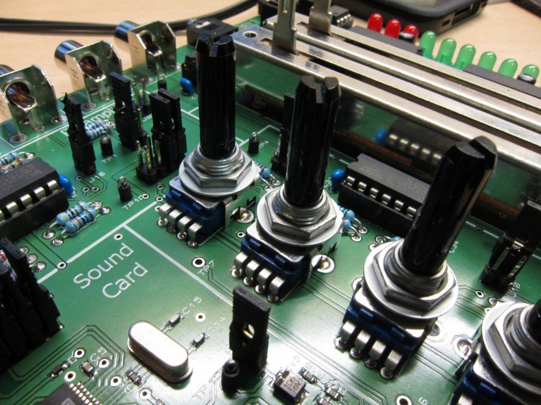
First I removed all the surface knobs and fader sliders (carefully prying them up with a flat head screwdriver resting on a piece of cloth to protect the controller’s surface), then I opened the back of the unit by removing the 22 screws (they really do not want you to open it up!, Pic 1), please note that the last of the screws is hiding behind the NI sticker (once you pop a hole through that there is NO turning back, no more warranty!). Inside there are a total of 6 separate boards connected by their respective wiring: (uppermost: Sound card, bottommost left: Phones/cue/vol/Mic board, bottom middle: Replaceable crossfader, leftmost: Deck board, rightmost: Deck board, middle: Mixer board, Pic 2). You can easily remove the sound card board by removing the two knobs from the back of the unit (input gains) and the two screws on the inside. I found it to be a good idea for me to take pictures of the process and label all the connectors with a numbering system as I disconnected them so that later I knew what connector went where… there are a lot of cables in there (Pic 3)…. The sound card board is also where the USB connector is located (Pic 3). I then removed the two bottom-most boards by removing their respective screws. The crossfader was absolutely disgusting (Pic 4), no wonder this unit had issues…. After removing the three boards (sound, cuemix and crossfader), then you can start the process of removing the deck and mixer boards (Pic 5). Again, NI does not make this easy at all. Even though there are a number of screws that hold the board in place from the inside of the unit you CANNOT remove any one of these boards UNTIL you have removed the pot fasteners from the top of the unit and you CANNOT remove those fasteners until you first remove the two metal faceplates off the decks and the middle plastic faceplate from the mixer :rage: This is probably the most frustrating and slow part of the disassembling process. Those faceplates are attached to the plastic frame by very stubborn glue. I was able to remove them with a thin kitchen knife and lots of patience (Pic 6, you do not want to rush this, you can end up bending the metal faceplates or scratching/breaking the plastic one, patience and manual dexterity are key, slow and consistent prying pressure from many different angles will eventually get them off). Once those were off, I removed the fasteners (washer and nut) from each of the pots in the mixer and then from the two pots in each deck (Pic 7). At this point I returned to the back to remove the screws from the MIXER board. I removed it by first disconnecting the cable to the left and right jogs (I had to make sure I labeled those wires since I did not want to confuse them) as well as the cables to the left and right deck boards. The mixer board came off with the four volume faders (these faders are not replaceable unless you are willing with unsolder them, Pic 8). Then I removed the left and right jog wheels by removing the screws that attached them to the circular plastic frame. I removed the left and right deck boards by removing their respective board screws (each of the locations on the boards where the board-holding screws are located is indicated by a picture of a screw next to its hole (at least that was helpful). After that I removed all the plastic button matrices (hotcue/samples and cue buttons, Pic 9). I was able to disassemble the jogs by first reversing the instructions provided by photojojo (S4 Jog Wheel Solutions- Recalibrate and Replace ) and then I turned counterclockwise the small square board located in the middle inside the jogs. Those small boards are attached to a screw and once loose it allows the two halves of the jog to come apart (Pic 10), once the jogs were open, I was able to directly clean a bunch of sticky mess clinging to the inside and the grooved wheels with a DAMP cloth with warm water and diluted dish soap (60%water/40% soap).

Dismantling, cleaning and reassembling Kontrol S4. Part II

Once I had the entire unit disassembled, I then cleaned everything that I could:

  1. All the plastic knobs, sliders, buttons and empty plastic frames were soaked in warm water and dish soap, washed by hand with a toothbrush and allowed to air dry.
  2. All the screws, washers and nuts were soaked in 99% ethanol alcohol (although I believe that you could also use 91-95% Isopropyl as well, the higher concentration the better since it contains less water and evaporates faster without residue), rinsed with fresh ethanol one more time and allowed to air dry.
  3. Every one of the six boards were directly sprayed with 99% ethanol and washed with 99% ethanol and a toothbrush. (NOTE: since I had labeled the cables and connectors previously with a sharpie, I had to be careful/mindful of where I sprayed/poured the alcohol since it can erase the markings). There was a fair amount of a sticky substance on some of the board’s surface so the toothbrush was a great help to removed that. I also used the toothbrush and 99% Ethanol to clean each of the faders (including the crossfader) on the outside and the inside without disassembling them. I used the bristles of the toothbrush to reach inside the faders from the top opening while I repeatedly rinsed them with fresh ethanol alcohol (Pic 11). I did that until I was confident that there was nothing more that I could have cleaned. After finishing brushing all the components of each board (pods, buttons, etc..) I then rinsed the entire board with more 99% ethanol and allowed the boards to air dry (Pic 12).
  4. As I mentioned earlier, I opened up the jogs and cleaned them inside and out with a damp cloth to remove the sticky substance clogging up the inner surface and its gear surface that I believe is used to determine jog rotation via a light sensor (so if you are having poor jog response this might help alleviate that problem, Pic 13). I made sure NOT to remove the lubricant grease found in the middle shaft (but I could have replaced it with some silicone lubricant like the one used for SCUBA or camera o-rings) and to reassemble the jog before putting them back in their respective locations. The small square board/sensor on the top surface I cleaned with 99% ethanol and a cotton swab.
  5. I only cleaned the front metal and plastic face plates with a damp cloth (warm water and diluted dish soap) and only the side-up face of them because I wanted to be able to reuse the glue still underneath the plates. WARNING: they are not going to stick with the same original strength and if you were not careful during the initial removal you will likely find some bending on the metal plates which you can somewhat rectify but it will NOT be just like it was before the controller was disassembled.

Once all the components were dried (~4 hours later since I was using high purity ethanol which evaporates very fast. But, if I had used anything else I would have waited much more time for the boards to dry, at least 24 hours drying time just to be safe), I then sprayed each of the pots with a little of DeoxIt D5 contact cleaner while I worked them left-to-right to facilitate penetration and I also sprayed inside the faders with two short bursts of DeoxIt Fader F5 while moving the fader control to distribute the cleaner/lubricant until a smooth glide was achieved.

When everything was dry and ready it was just a matter of reversing the disassembling steps, making sure to place everything in its original location (buttons, plastic LED light accessories), connect the cable bundles with their right connectors (hopefully), connect the jogs and each deck board to the central mixer board BEFORE I attached the middle mixer board, screwed the jogs back onto their respective plastic frame, then reattached the left and right deck board with their respective screws. After that I reattached the pots to the main plastic frame with their respective washer/nuts before I reattached the two metal faceplates and the middle plastic face plate with what was left of their original glue surface. Once all six boards were back in place and properly connected, I then tested it for connectivity before closing the unit by attaching the back case with the 22 screws. All that was left then was to re-install each of the plastic knobs and fader sliders.

It was a day-long DIY project (total of about 6 hours from beginning to end) but now I have a fully working S4 controller with one exception: no matter how thorough I clean it, the volume fader for track A is still acting up, I have recalibrated everything at least 15 times but only that one particular fader continues to lag in response (I can work around it for now plus everything else on this unit now works 100%) so I am convinced that it is a hardware issue (worn-out fader?). If I can find a source for those alpha volume faders (B10KX2) I would not mind desoldering the faulty one and soldering a new one on (maybe by then we can get our hands on the mini-innofader that people are taking about but not yet available to the general consumer). Also, I decided that I need to mod my controller case to make the top faceplates easily removable without glue so that I do not have to deal with the pain (and the likelihood of damage) of prying the plates every time I want-to/need-to get to the deck or mixer boards. I am open to suggestions…. :smiley:

BONUS: So, if you managed to read this far, first I have to thank you and second you are probably wondering what happened to the broken USB connector (Pic 14). Well, from reading previous postings on this great forum, from a post by kaleaf in a related thread I found that it can be replaced (Accidentally Broke VCI-100 USB Connector ) with some desoldering and soldering involved. That is what I did. I have no previous experience with desoldering and very limited experience with soldering anything (half of those experiences were not a pretty sight) but I went ahead and ordered the USB B female connector part ($1.25 USB Female Type B Connector - SparkFun Electronics) and bought a desoldering tool from Radio Shack ($12.99, http://www.radioshack.com/product/index.jsp?productId=2062731 ), a desoldering braid ($4.49 http://www.radioshack.com/product/index.jsp?productId=2062744 ) and used a 30Watt soldering iron I had at home. I watched some DIY videos from Youtube on proper desoldering techniques/tools and then I de-soldered the broken connector from the sound card board. I used the desoldering pump to remove the solder from the four central small pins and used the desoldering braid to remove the solder from the two larger attachment points of the old connector to free it from the board (Pic 15). Once it was removed I cleaned the area with some 99% Ethanol alcohol, let it dry and then soldered the new USB connector in its place matching the location of the pins to the same as the previous broken connector. All in all it was actually a relatively straight forward fix even for someone with limited soldering experience like me (Pic 16).

Super Bonus: since my S4 did not come with a power adaptor, I found one that matched the specs of the original (9V, center positive, at least 1200mA). For those of us stateside, you can find a universal AC adapter at your local Walmart for ~$18.88 (Robot or human? ). I bought one and once set up properly (correct voltage and polarity choices; it comes with seven different connector tips but the one that fits the S4 is the largest one) it works with my S4 controller without any issues so far (Pic 17). I am happy :smiley:

For the lawyers among us: if you are considering opening your NI Kontrol S4 by trying to duplicate this narrative you would have to do that assuming all potential damages to your person and/or equipment under your own risk and free will since I am not responsible for any damages and injuries.

I hope this information is interesting to some of you and I would like to thank all the people that have previously provided information on this forum from which I learned a great deal.

IKU

This a very brief and handy report. I enjoyed reading it!

It’s awesome!

Thanks for the excellent write up!

Hello everyone:

I apologize for having to post it via two separate threads (part I and part II) but when I tried to first post it as one single article it was way too big and it would not let me.

There are a couple of things that I should add to the information previously posted:

A) There are actually seven separate boards inside the S4, I left out the one that holds all the pots for the FX units and the deck gains/master level. It is located on the top-most section of the unit, just after the mixer board. It can be removed and reassembled just like the mixer board (i.e. removing the front face-plates, then the fasteners for each of the pots). I actually did not mess with it much since it looked clean and I think there is plenty of truth to the old saying: “if it is not broken, don’t fix it”. So, I left it alone, just sprayed it with 99% Ethanol and left it to dry with the main plastic case.

B) In order to remove the Phones/Cue board you first have to remove the plastic knobs from the controls (Cue Mix, Cue Vol and Mix Vol), then push-in the metal masts to lock them in their “recessed” state so that they do not interfere with the board removal and finally remove the nut around the phone’s connector. The board should easily slide up and out (no screws holding that board down).

Well, I think that’s all for now.

IKU

Thanks for the pictures, will be keeping for future reference. :slight_smile:
Looks like the S4 uses the same pots as my hardware assignment so I’ll know where to go for spares:

thank you for this post! very interresting !

Merged the 2 halves. Nice write up, thanks for posting.

Wow. Cool post and good job.
bookmarked for reference.

I take apart computers to clean but I dont think ill ever try this on my s4.

And the circuit board looks pretty straight forward. They shouldve made it easier to access :stuck_out_tongue:

Anyone know if you can get the potentiometers Stateside somewhere?

Looking at a couple S4s but they have broken loop and/or size/set knobs.

I’m fairly sure the S4 uses ALPS pots if that helps.

This looks like the one :+1:
http://www.alps.com/WebObjects/catalog.woa/E/HTML/Potentiometer/RotaryPotentiometers/RK11K11/RK11K11_list.html

It seems like the S4 has 3 pin and 4 pin pots though.

3 pins for the loop/transport knobs and then 4 pins for the EQ knobs.

I saw your post over on NI, but that was in Greece :confused:

Thank you though, would you happen to know any of the other specs like turns, resistance, etc.? Or should I be able to identify that from the pot.

Well the loop/transport are entirely different as they are metal? shafts and are encoders rather than regular potentiometers.
Could be one of these: http://www.alps.com/WebObjects/catalog.woa/E/HTML/Encoder/Incremental/Incremental_list1.html

If you’re thinking of replacing pots you should already have a multimeter capable of measuring resistances - I don’t have an S4 anymore to test myself.

Ahh. Didn’t realize they were different.

Well, eBay decided it for me and I didn’t win the auction unfortunately :disappointed: Gives me some time though to research this more.

thanks for this- very informative of some of the things i will be facing if i try to open my S2. I’m considering doing so to spray some electrical cleaner under my cue/sample buttons, but am wondering if just shooting it through the cracks in the face would do the trick or if the buttons can be removed from above. any advice?

Hi,
Thanks for this. Anyone have any extra tips for getting the faceplates off?
Got my Faceplate off, just had to grow a pair. Now, i need to get my slider’s case off, preferably without having to de-solder…

It worked!!! But now my FX knobs are going nuts…LOL… Opening her back up…

fail.
I guess im just sending it in to NI…

Thanks so much for posting thing! I read this about a week ago and was terrified… but today I bit the bullet and got it done. One of my line faders was glitchy, as well as my crossfader, and I’d tried compressed air, tried vaccuuming, but neither helped.

I followed the instructions to tear down, and it’s actually not as scary as it sounds. Removing the metal and plastic face plates are tricky, but not terribly so. Just take your time. I got the second metal place off in about 5 minutes, with a combination of small screwdrivers working things back and forth. Also of note is that if you only need to work on your line faders, then you don’t need to remove the metal face plates at all, just the plastic plate in the middle.

I used compressed air, some rags, and MG Chemicals Contact Cleaner to thorough clean out both the crossfader and the line faders. It’s easy enough to remove the metal casing on the crossfader, but a pain in the butt to do so for the line faders, and I didn’t have the courage to desolder them, so I just cleaned them in place. Upon re-assembly everything works and there’s no glitching!

Also during re-assembly, I didn’t bother screwing down the pots underneath the metal face plates, so if I ever need to remove those boards in future, I won’t have to trouble with the faceplates.

I’ll upload a video shortly.

Here’s the vid:

Thanks again for the instructions!