…
At U-hid page says that you could set them as “mouse axis”
![]()
…
…
At U-hid page says that you could set them as “mouse axis”
![]()
…
No way to seperate mouse input within Windows and no way to bind a particular axis to a particular deck within Traktor ![]()
However, I am now searching for a different solution. I already had the first Powermate from a while back, but I didn’t know until today that Griffin doesn’t sell them anymore.
Ordered some more parts from Sparkfun:
14x Rotary Potentiometer - 10k Ohm, Linear
25x Blue & 25x Green Superbright LEDs
2x sets of 10 .1" Hookup Wires
5’ x 1/4" Heat Shrink Tubing
2x 10 Segment Blue LEDs
The 10 Segment LEDs will be incorporated into a VU meter at some point. They’re pretty cheap from Sparkfun, so I ordered them now since I was grabbing other stuff anyways.
I updated the original post a bit with some more information and to reflect the new parts.
God I love Sparkfun!!
Sparkfun sounds cool…
how are you getting around the windows limitation of 8 analogue inputs (potentiometer) via HID usb? it looks like you’re planning on using more than 8?
I love you.
Sparkfun is definitely the place to go if you need parts!
Windows supports 8 inputs per joystick, this is true. But it ALSO supports multiple joysticks ![]()
<3
…
I understood at u-hid page that every spintrack will be a “separately” axis (mouse have two) and you could implement in their software the mouse function… Traktor doesn’t permit mouse scratching? It could be possible make a “click macro” every time you touch the encoder (or put a capacitor over the scratchpad) that send this “stroke” (with click and window position) such as mouse scratching (but a bit accurate…)
![]()
Download the configurator program and check their possibilities before discard… if not I will help you in find new “core”.
…
Much progress this weekend. Received parts from Sparkfun and learned a few things the hard way about cutting 1/4 inch acryllic.
Sparkfun delivers!
10k Pots
Jumper Wires
LEDs
Heatshrink Tubing
I started cutting the holes for the arcade buttons with an 1/8 inch pilot hole and then a 15/16 inch Speedbore on my drill.
Got the first 5 holes cut out no problem.
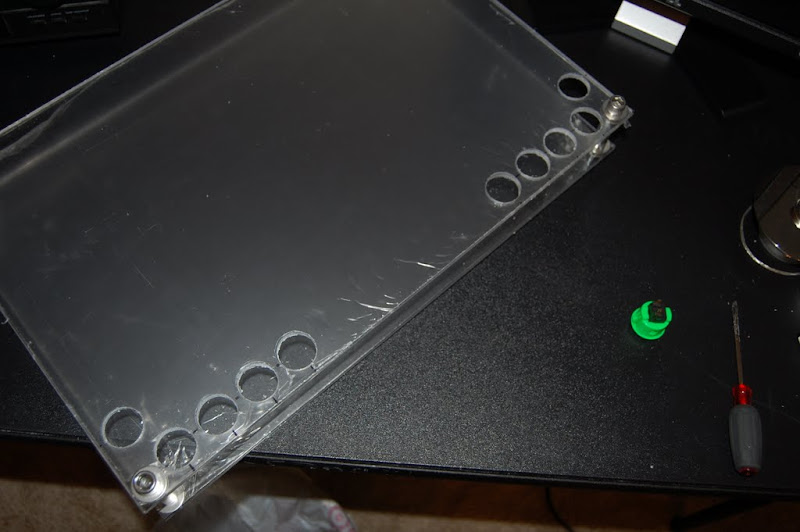
Then when I moved to the other side, this happened on the first one. It spidered across to one of the pilot holes I had drilled.
So that kinda ruined my evening. Went to Lowe’s a couple days later and bought another 24x18x1/4 inch sheet and had it cut in half like the first one. Now I have a spare if I trash the one I am working on! While I was at Lowe’s I went ahead and picked up a 1 inch hole saw as well. The Speedbore was slow going and also is the reason the first panel was ruined.
The difference between the holesaw and the Speedbore is amazing. Cutting the holes is a cakewalk and appears to be much less stressful on the panel.
So far so good…
Measuring the other side.
Success!
Time for a tasty beverage~
Next I measured and drilled the 5/16 inch holes for the center EQ.
Measuring and eyeballing the FX knobs.
All the EQ and FX holes are drilled.
They look rough, but its just the plastic film that covers the acryllic. Here you can also see the small hole I drilled to a depth of about 1/16th inch for the locating pin on the 10k Pots.
Beer break!
Mounting the 10k Pots.
All the 10k Pots are in.
Micro ATX power supply mounted. This will supply 12v for accessories and possibly lighting, 5v for the powered USB hub, and 3.3v for LEDs and any additional components that require low voltage. It uses an external brick that supplies 12v DC @ 5 amps. More than enough juice.
Top panel in place with power supply.
It’s close, but there’s room to spare. ![]()
Mounted the UHID board right in the middle of the bottom panel.
Time to get started with the wiring. First task is to connect ground wires for the arcade buttons. The UHID board works by watching for it’s input pins to be pulled to ground, so all of the arcade buttons can easily share one grounding pin. I will then connect each of the other terminals on the buttons to their own input pins on the UHID. Here I have soldered on the first set of ground wires.
1/8 inch sleeving and heat shrink in place. I like the look of the sleeving!
And the first grounding spider is fully assembled
I cut one of the jumper wires from Sparkfun in half, and soldered it to the spider. Sleeved with heat shrink of course!
That’s it for now! Both arcade button ground spiders are assembled. Next weekend I will work on wiring the 10k Pots. So far so good!
I also did some testing with the UHID and Rejoice. M-Joy is not going to work, so I had to find a different HID-MIDI converter. Rejoice works like a CHAMP! I can’t wait to finish this controller and put it to work!
great job so far!
Excellent build log. Keep up the good work.
Nice work, keep it up.
Do those rotary pots have a center detent for the eq section?
If not might be worth looking for some that do.
Thanks guys!
They do not have a center detent. I looked for some briefly, but the ones I got were extra low cost. I have a software detent in that I set up the center of each axis to have ‘gravity’. It’ll work for now, but I will probably swap in better pots at some point.
Judging from what I’ve read from the reviews on that button it’s a replacement for the X-Box controller buttons. Would it be possible to buy broken controllers off of Ebay to supplement your buttons? If you could find old ones with damaged cords, you may be able to desolder the buttons for next to nothing.
Only thing is I don’t know how they are mounted in the controller. Hell, you may even be able to use the rest of the controller as a brain for some of your other pots, buttons etc.
The main reason I can’t use buttons out of a broken controller is because 99.9% of the time they are membrane buttons. Basically on the bottom of the button itself is a small piece of electrically conductive rubber. When you press the button the rubber contacts a pair of bare traces on the controllers circuit board which completes the circuit.
In order to use the buttons, I would have to etch my own circuit boards with the correct tracing to make it all work, which is beyond my ability right now.
I think I might have a winner though from a site I just found right now actually.
Ordered Faders and Buttons from http://www.futurelec.com.
Long 10k Faders for Volume:
Short 10k Fader for the crossfade:
Small buttons:
More to come!
Cool! Would really like to see the end result ![]() .
.
already loving your project!
…
Good Job man!
…
Thank you all! I can’t wait to finish it myself, should be a blast to use! Just wish I had more time to work on it, but my day job keeps me on the road a lot. Oh well, more to come!