[DIY] "Generic midi controller" *Build-log*

[DIY] “Generic midi controller” Build-log

The “Generic midi controller”

I’ve been researching DIY midi controllers for as long as I am a member of DJTT. However it has always been difficult for me to settle on a design that really suits my needs instead of a quick project that I do not actually need. One thing I notice a LOT is that I would like to have a dedicated controller for my effects that enables me to control all of them without the need for shift buttons or weird button placement. I think this design is the solution for me. This controller is going to be placed behind a standard 12" mixer.

Design

First of all I would like to thank DJTT for the design pack for the “Midi Fighter X contest” that helped me create this.
Here it is:

Schedule

25-07-15 Order all parts (buttons, pot’s, teensy)
10-08-15 Complete design in auto cad for lasercutter
15-08-15 Finish and order PCB
25-08-15 Cast buttons in custom mold.
01-09-15 Send files to lasercutter (and possibly 3d printer)
20-09-15 Finalize software design

Technical details

Brain: Teensy 3.1
Material case: Three layers of 2mm acrylic

28/8

Ordered all parts except for the arcadebuttons (they are out of stock) just started on the first PCB design and have just finished the top layer of acrylic:

29/8

Ordered the fist PCB: (professionals be like :unamused: when they see this)

30/8

Made a concept for the 3d-printed case, final design is going to be made in autoCAD:


Finished the design in autoCAD but upon requesting a quote it appeared to cost $276.83 so I’m going with bent acrylic

31/8

Ordered the Chroma Caps:
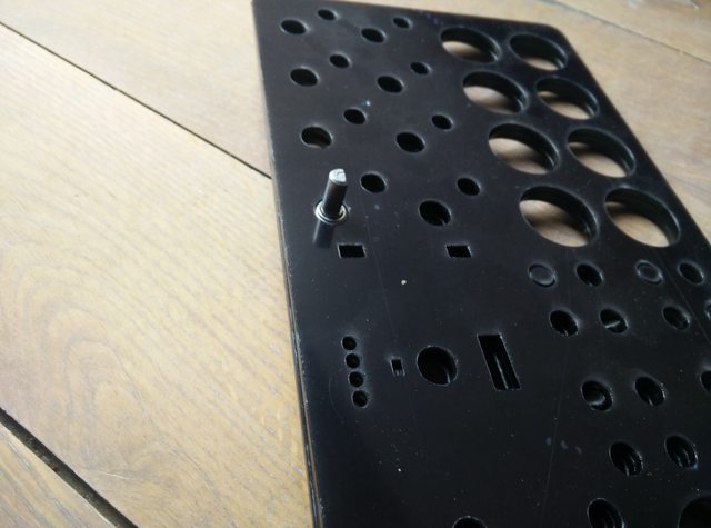
12/9

Received the lasercut parts: (final device is going to be gry with red):
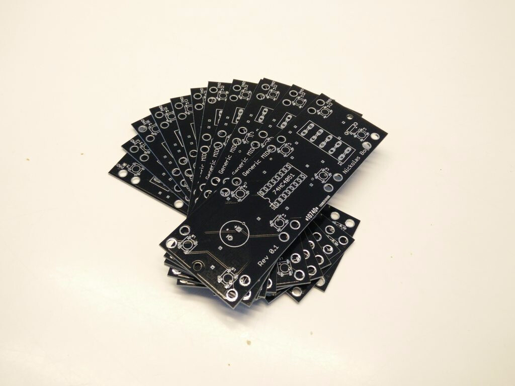


09/16

Got the PCB’s in the mail, going to check them later but they look OK.
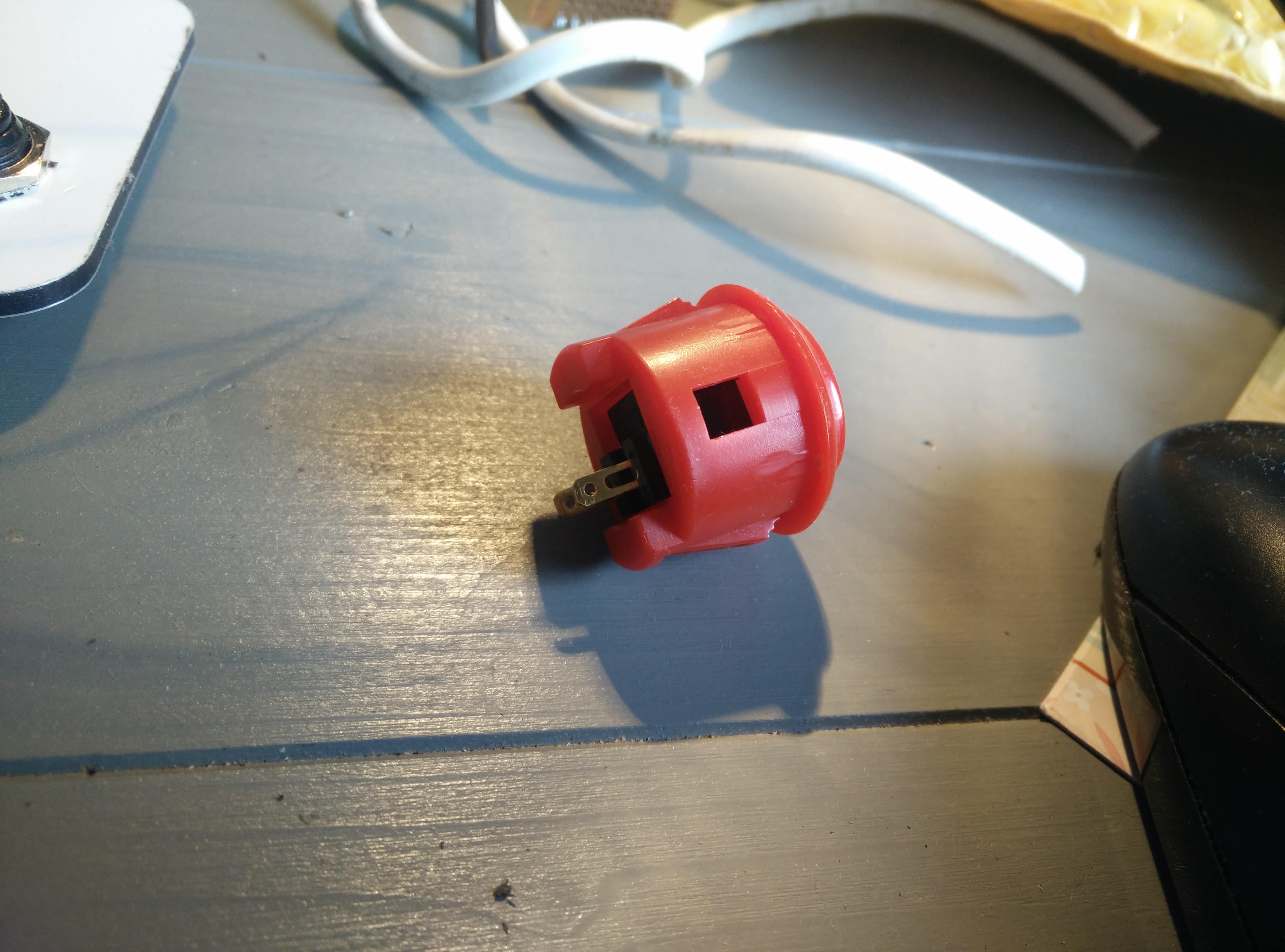
09/17

Got the buttons from focus attack for… here it comes… $7 a piece! wow! this sucks

This however does not:
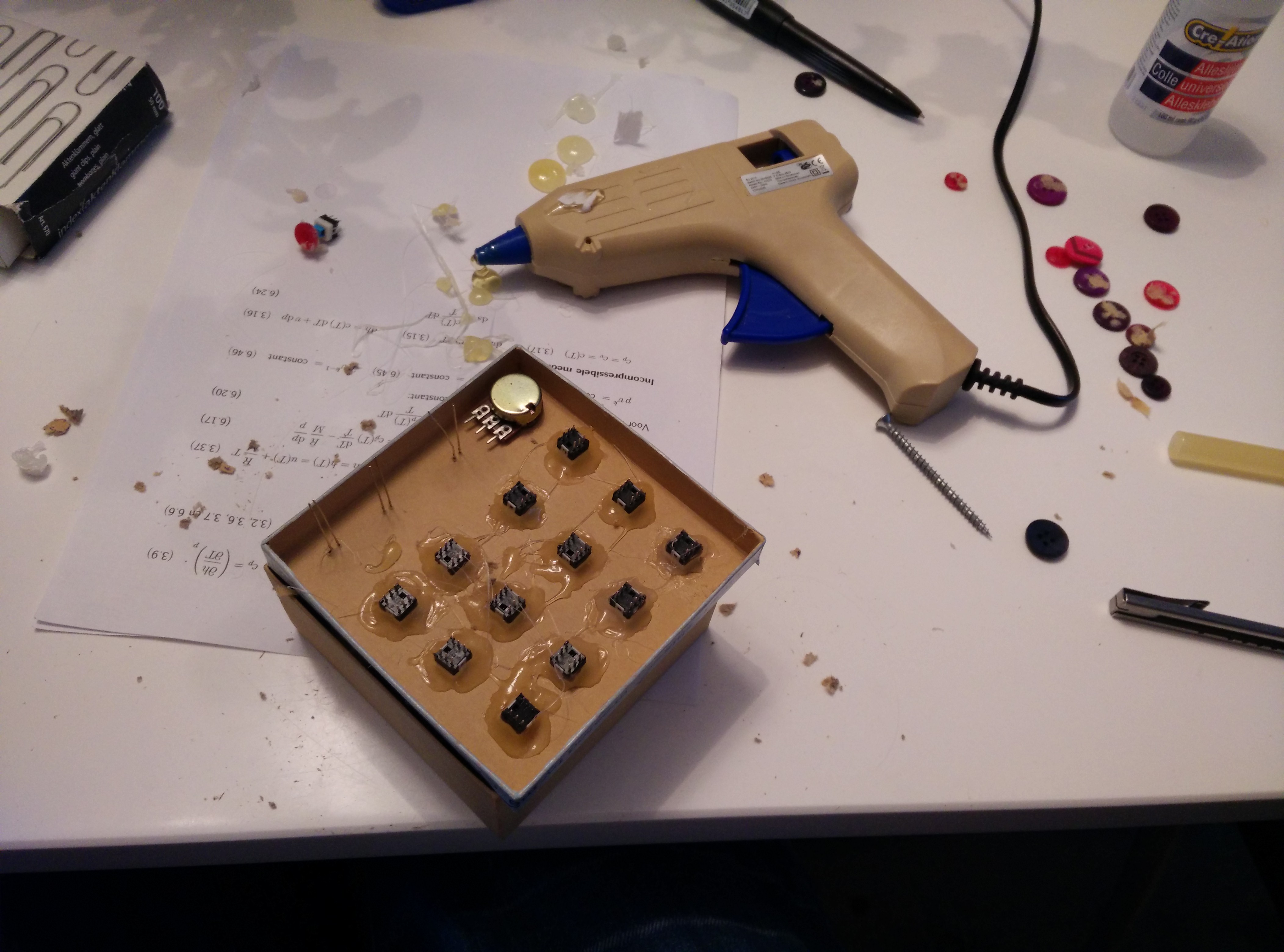
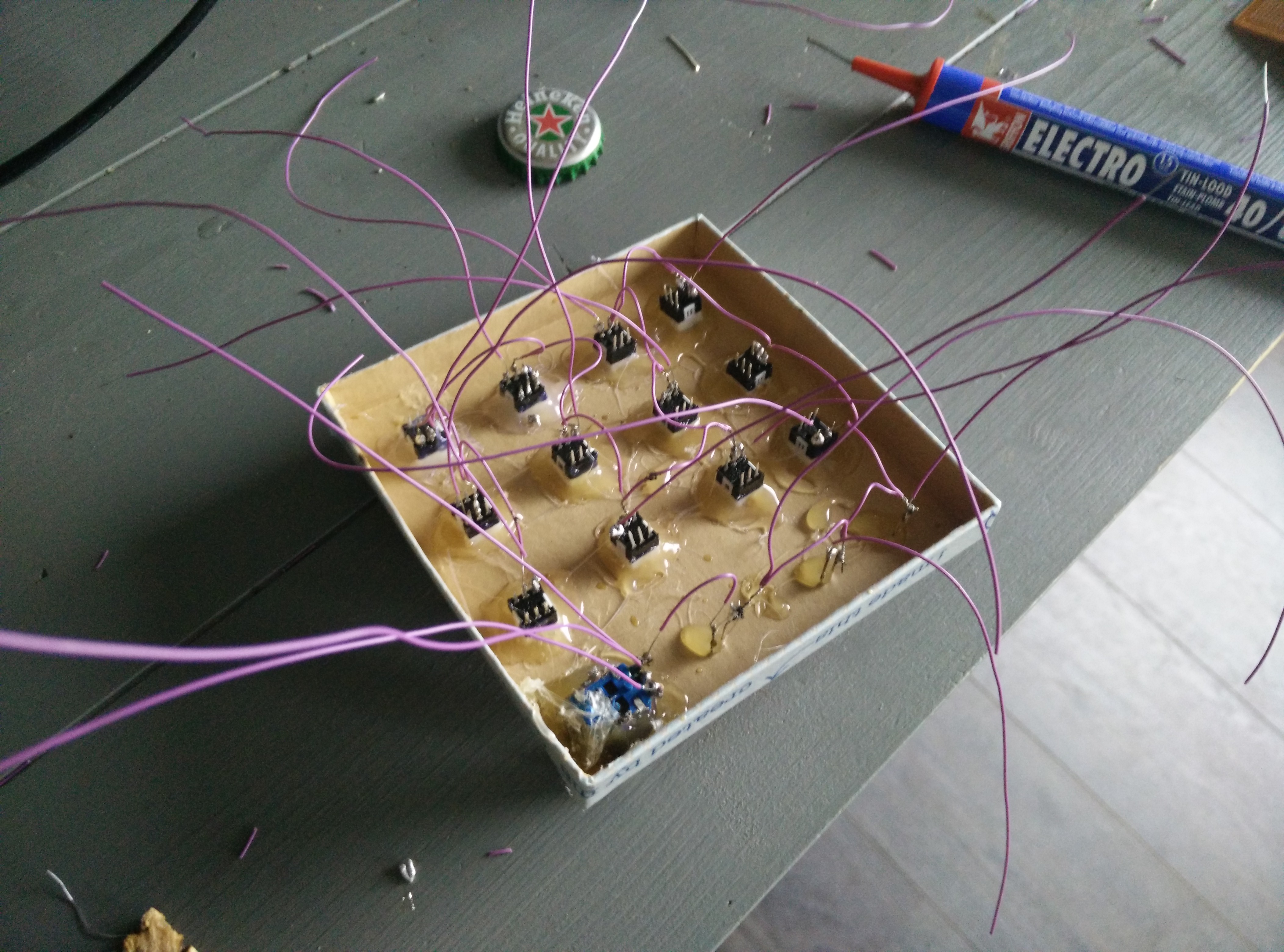
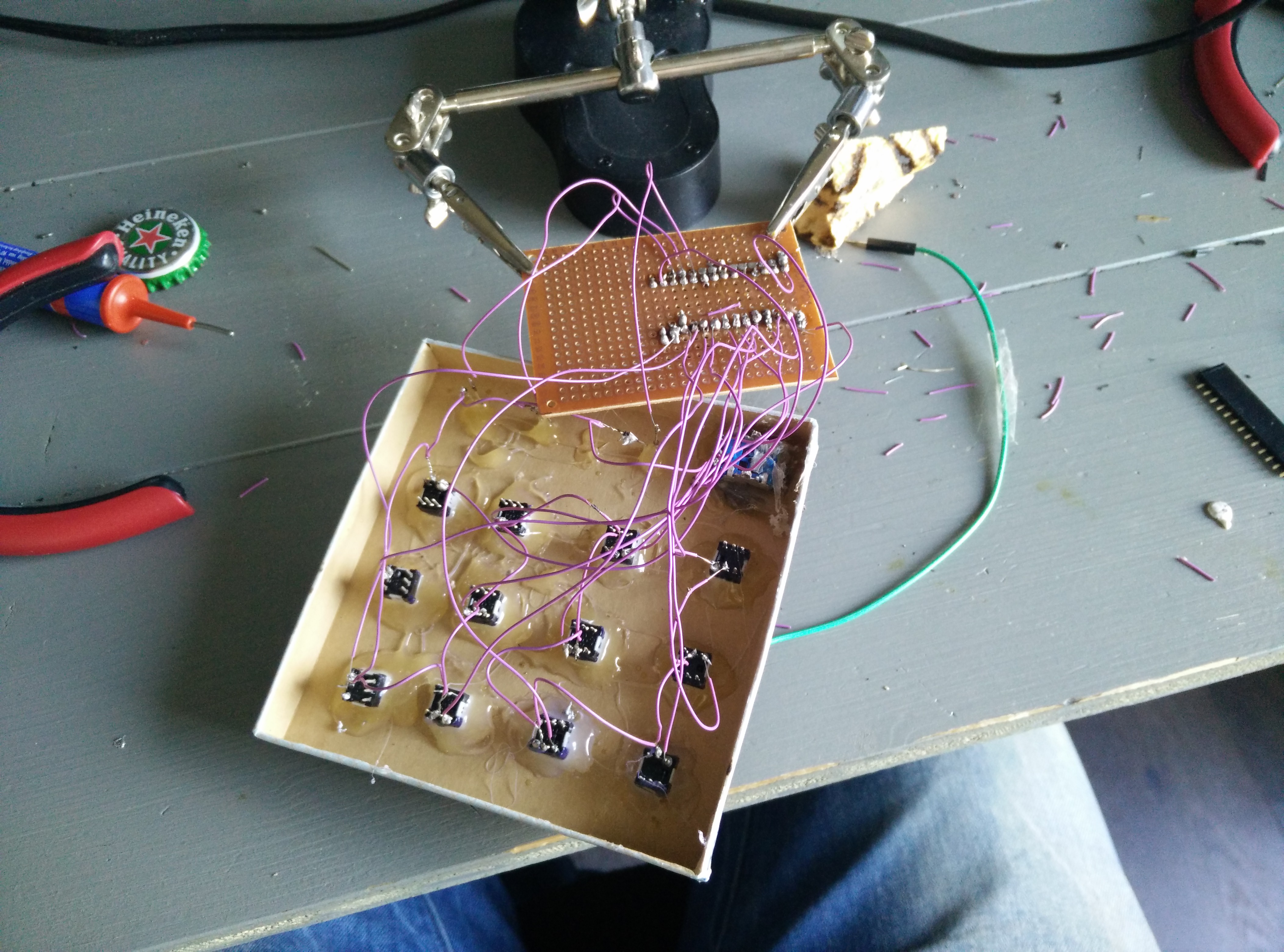
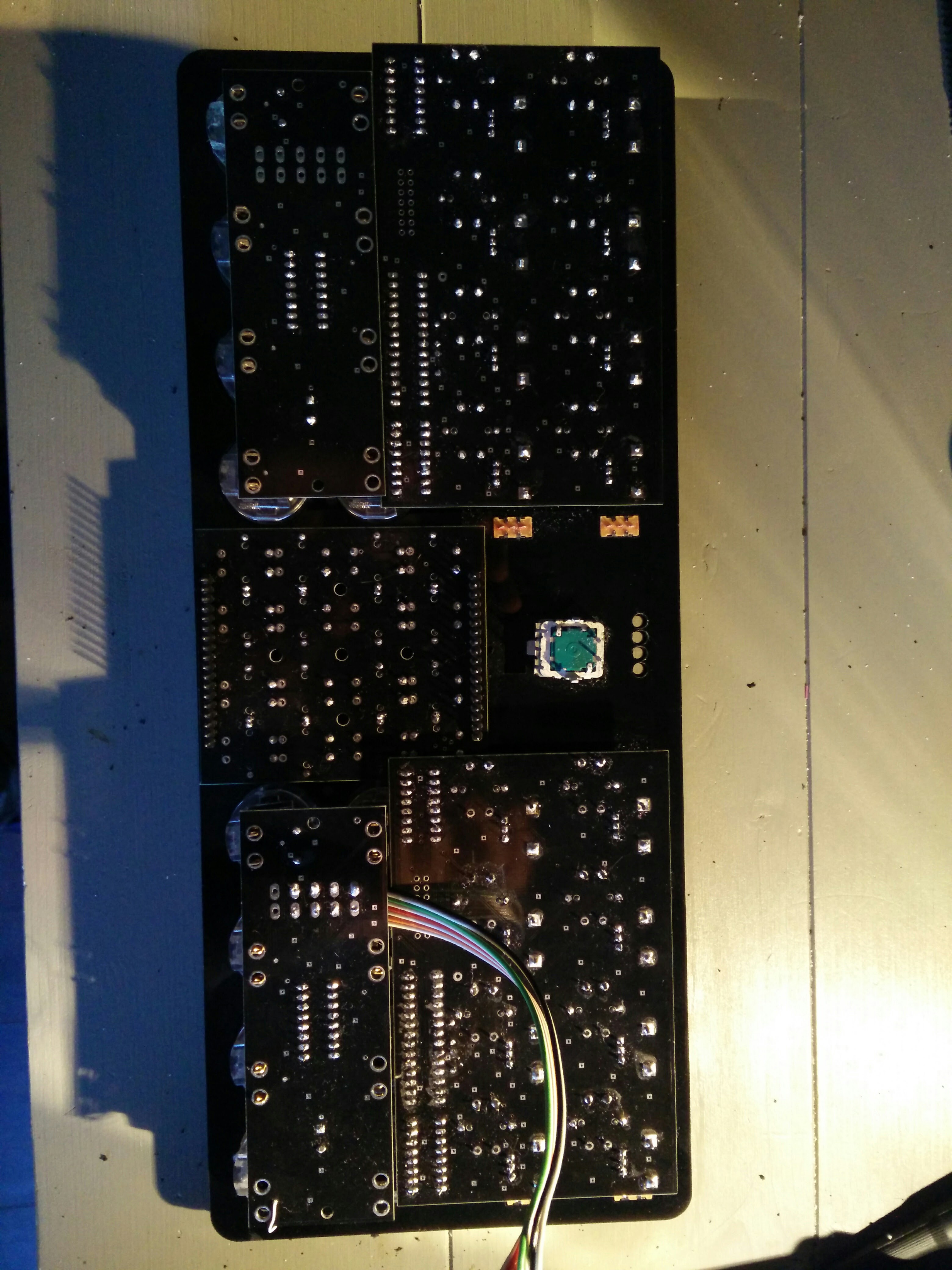
09/19

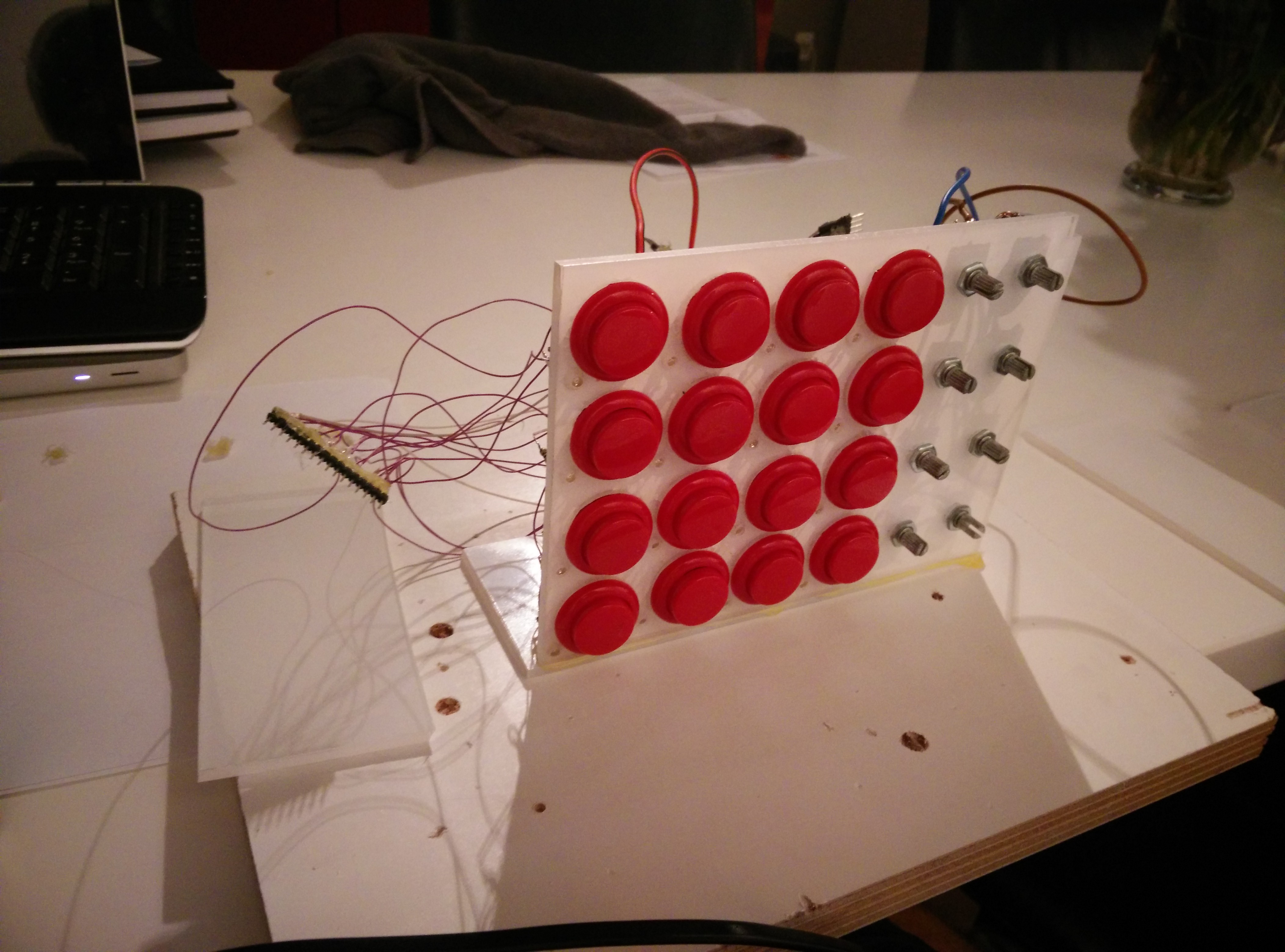
Assembled the button PCB’s and tested them:
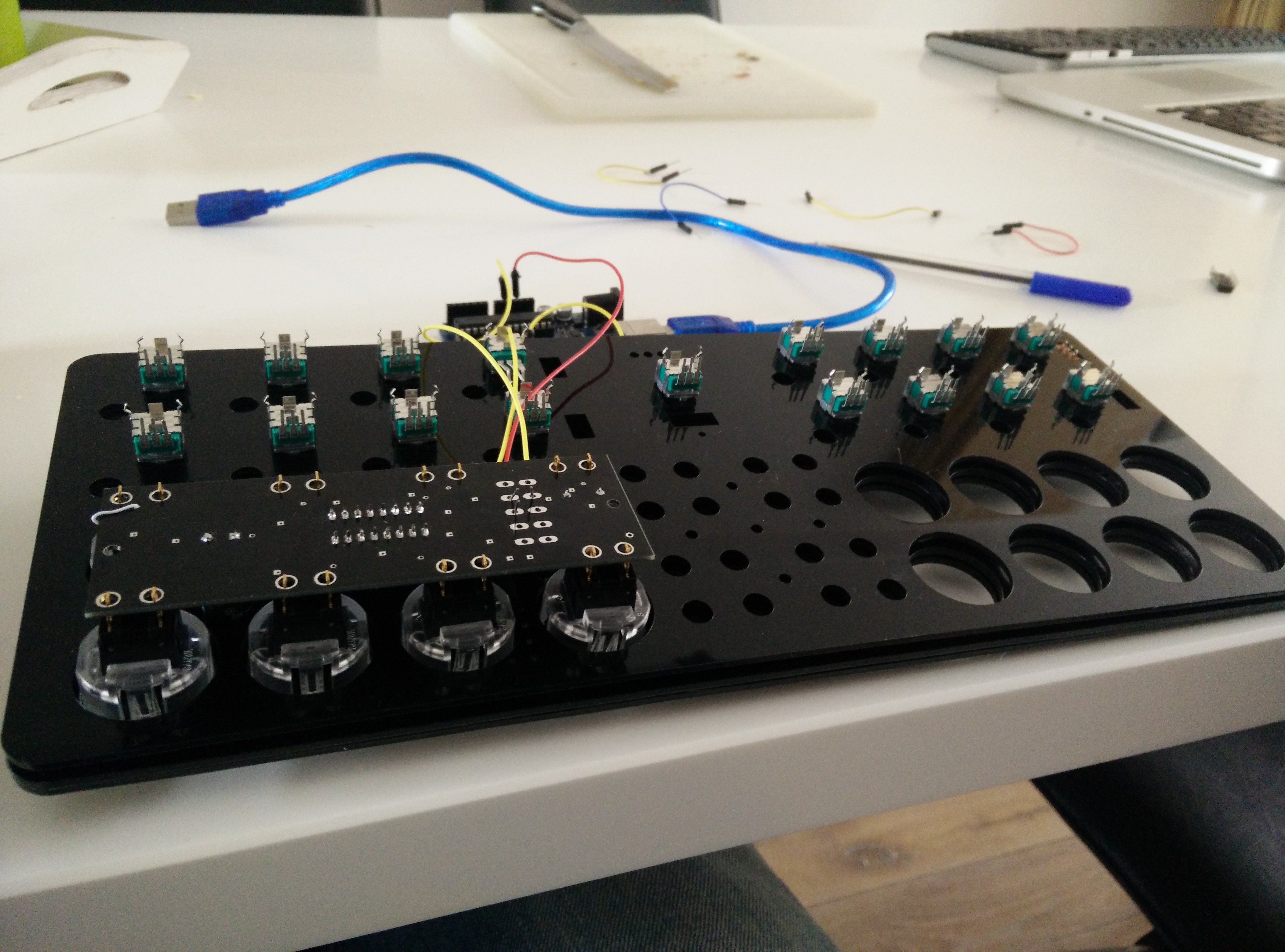
10/02
Finished the PCB for the potentiometers.
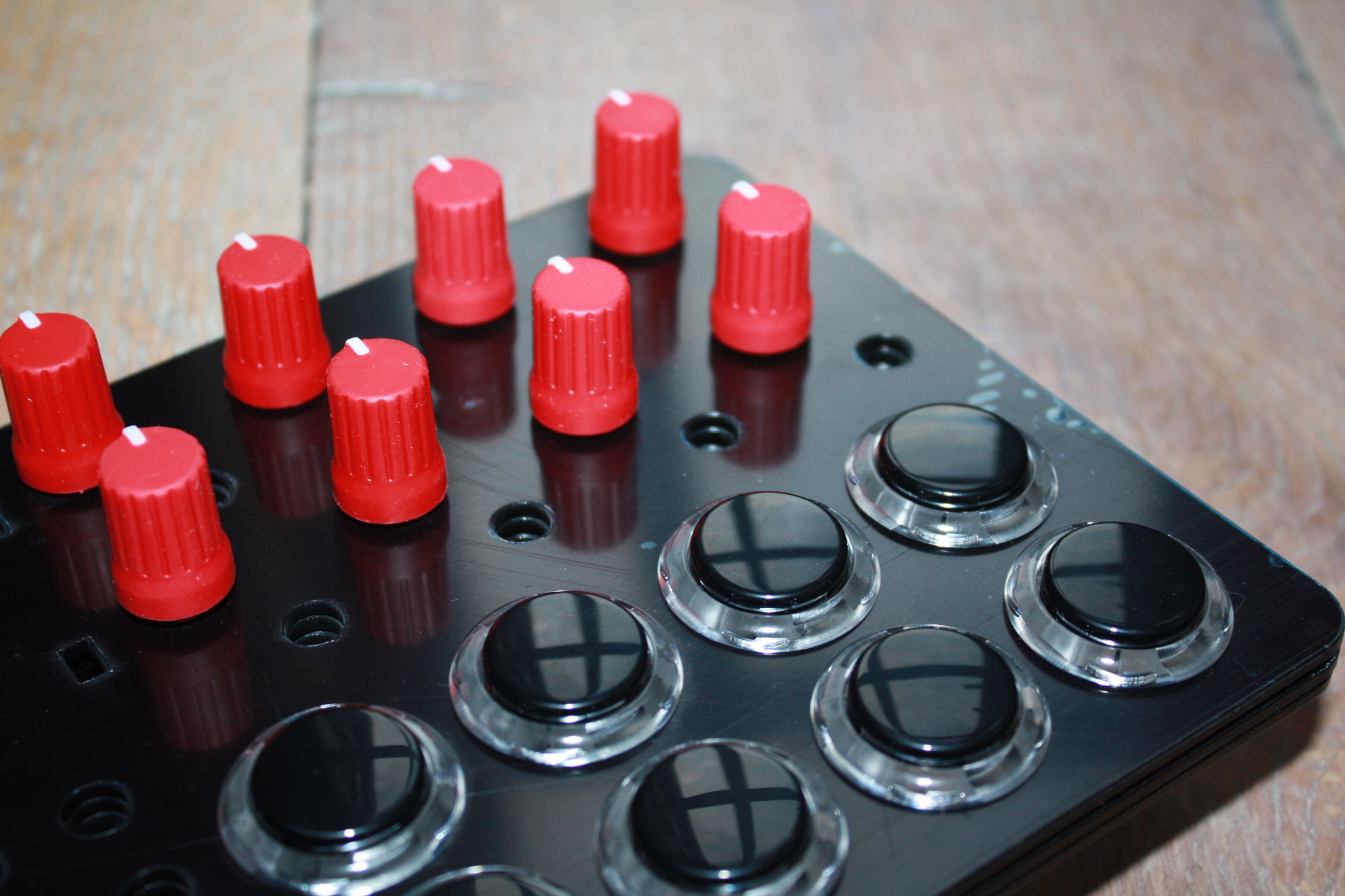
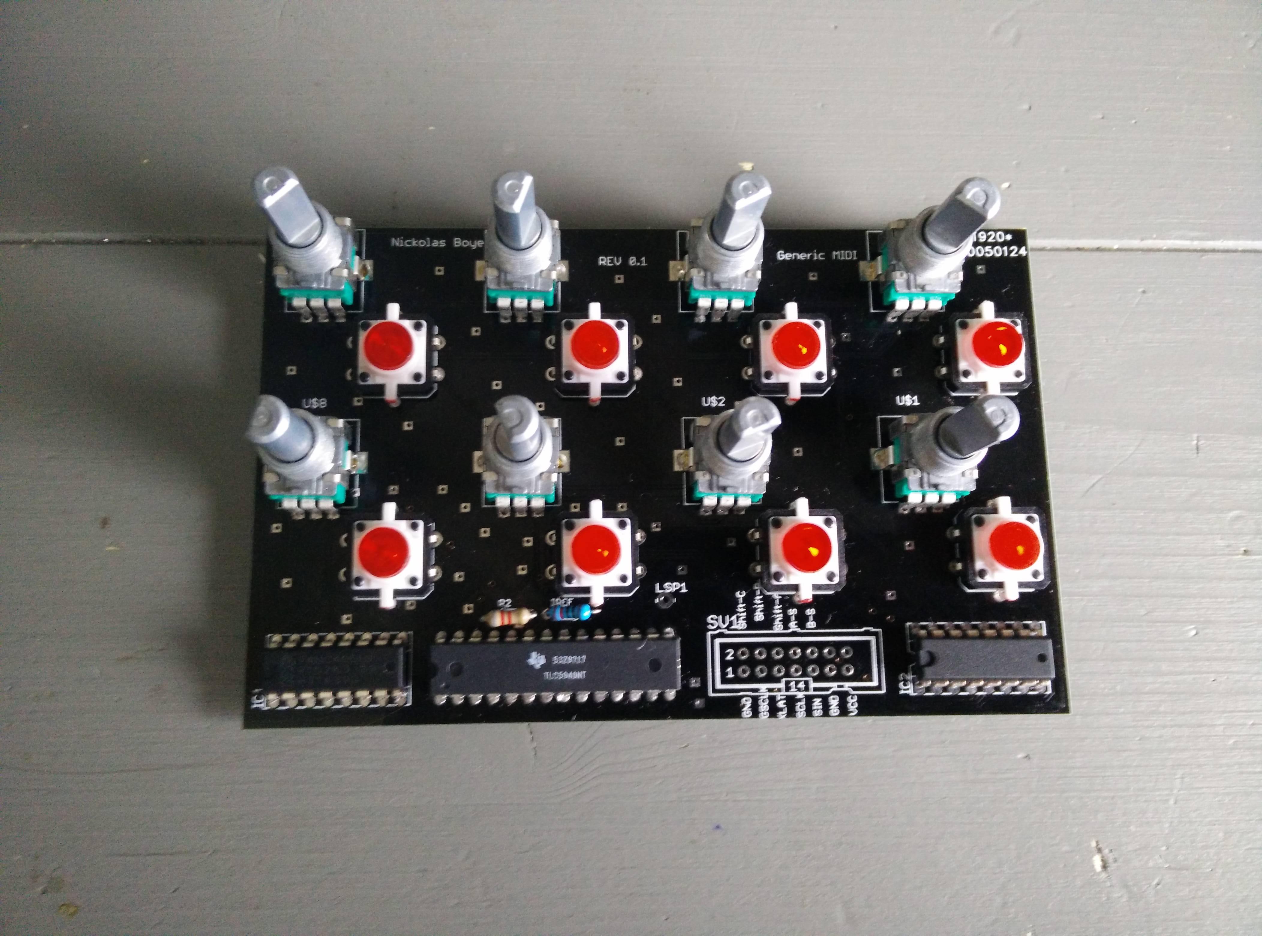
10/25
Assembled the PCB for the Pot’s:
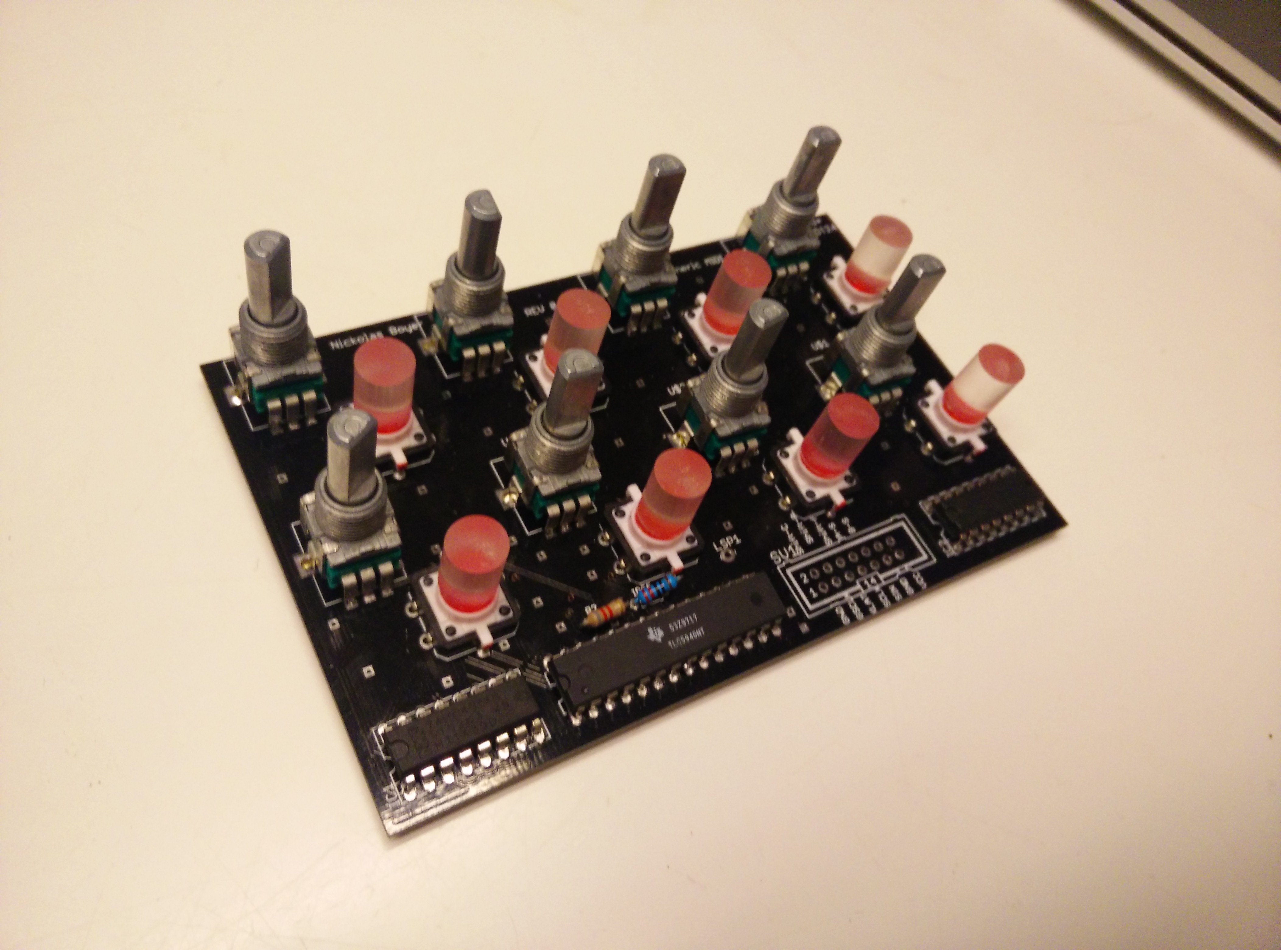
11/7
Finally found a place that sold transparant plastic (acrylic) rods with a small diameter in small quantity’s, had to enlarge the holes though (with a drill bit 0.5 mm a time * 80 times) then i had to saw this rod in tiny matching pieces (saw, sand the end of the rod and saw the next piece using a saw box). Then I used superglue to glue these on, on the first two i used too much so I had to remove these buttons.
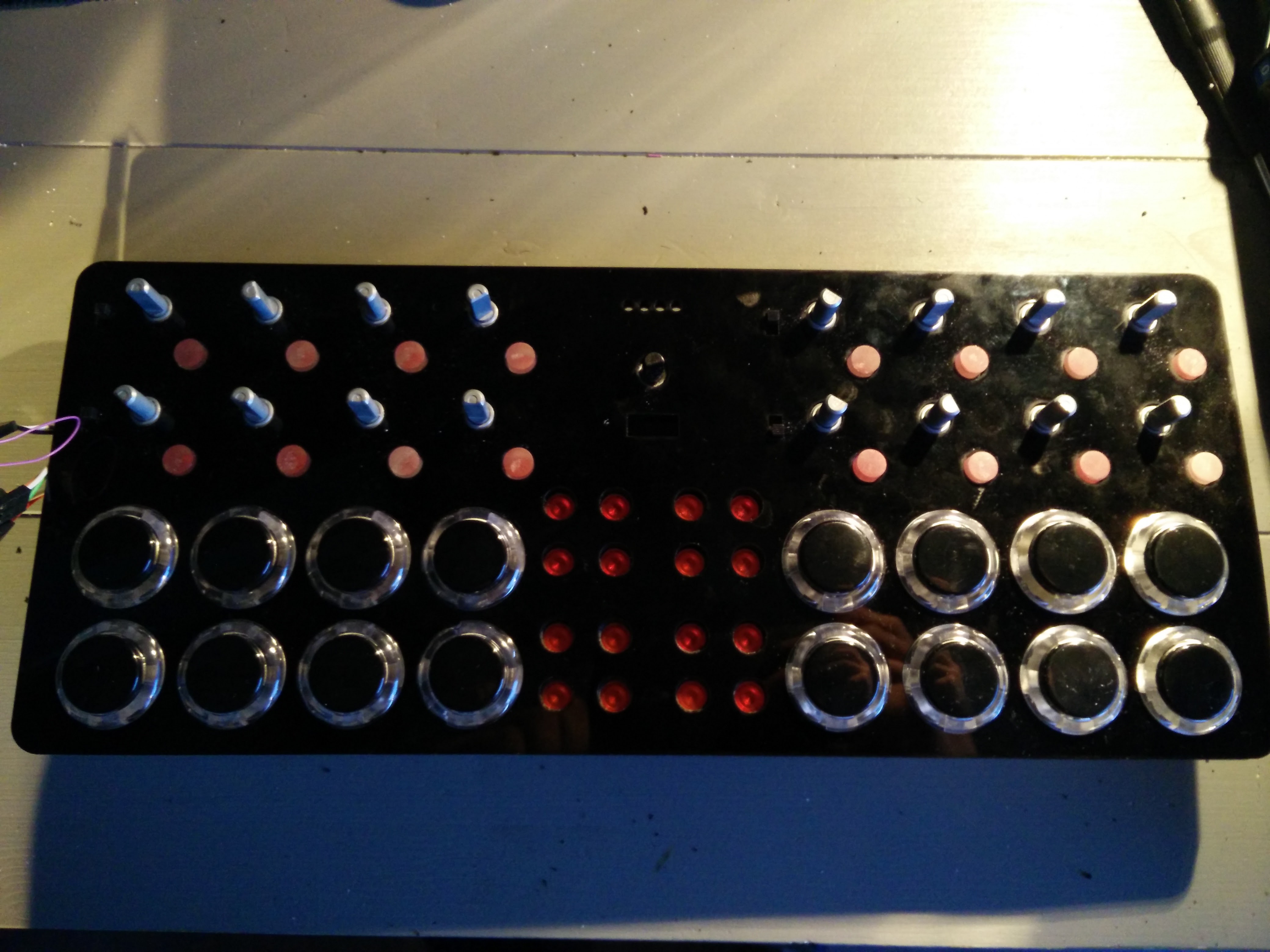
11/14
Finished smaller buttons:

20/01
Shitty pic’s are better than no pic’s :smiley:, progress is slow especially since I’m in the middle of moving to Leiden.

03/11/2019

I ended up crashing really really hard with the smaller button problem, the acrylic solution was horrible and the shit quality of the led buttons didn’t help either (also I made the design waaaaaay to cramped). At some point I even bought a 3D printer in order to print a mold and fill it with silicon to produce some better buttons. The silicon fluid has since gone bad and my 3d printer has not been used yet. On top of this all I’m constantly traveling so I never get settled enough to actually unpack all my hardware tools. Yet, my will remains strong, I will persist and I will finish this one day. I’ve moved this entire blog post to my personal blog just in case but I’ll also keep updating this build log here.

Much love and cheers!

reserved

Could you possibly build a second one? I’ve been looking around for something exactly like this for a while aswell.

Hey DoubleYou,

I’m wondering about the design fitting it to be placed behind the 12" mixer. Are you going to make a slight elevation, or legs, with regards to the cables and plugging?

that looks pretty cool :slight_smile: my recent solution was to buy a launchcontrol xl using 2 rows of 8 pots and the 2 rows of buttons. if ur into using remix decks its handy to have 8 extra faders or pots for their individual effects levels but i can see why u might not want that as part of your controller.

would probably work really well sitting on top of a reloop modular stand

Yhea zestoi had the same idea as me. A stand would have to be used unfortunately. Although all suggestions are welcome. :smiley:

Check out the stand that I have for the Zomo MC-1000. Something like this would be PERFECT:

The stand actually screws into the sides of the cotroller.

VERY sturdy.

This looks great!.. I’m going to copy this… like exactly.. :thumbsup:

This is what it looks like behind a DJM-850:

Just a little update:

Received my Teensy 3.1 and am now working on the software part

I want my controller to be as thin as possible so I experimented with some Sanwa OBSF-24’s and this is the biggest size reduction i could get away with (without reducing feel/quality)

The Teensy is so tiny, when I got mine with a bunch of ither electronic components I almost threw it away by accident.

Ok my little niece was visiting today so i made her a Midi controller that she could use while i was DJ’ing, used only scrap materials i had lying around (except for the teensy, that one is going to be used in another project :smiley:) Here are some pic’s and a vid of it in action.

First of all we hot glued all the components in place: (I ended up using a scavenged potentiometer from an old Behringer mixer instead to make it a true $0 controller)

The first components in place plus gluing on the buttons

Everything looks good, now lets begin on the inside:

This took a long ass time:

Connecting everything to the brain:

And the result!:

Here is a little vid of me using it:

Oh eh naturally a Parts List

  • Shitty buttons from a chinese RC controller
  • Clothing Buttons that were initially glued to the carton box
  • Carton box that contained some fair-trade tea
  • A Potentiometer from a cheap mixer inc. cap
  • Three brand new LED’s that you just wasted.

OK a little update, i had to gain some experience with the 74HC595 and 74HC4051 chips so i build me a little midi controller:

you can follow the progress here, I have no idea what Tumblr is meant for but it works pretty well for me

I really wish I had added some leds to my Midi Thug.

To be honest those 74HC595’s are killing me, i’m going to use ws2812’s or APA102/4’s for my final controller

first design for the faceplate, the final design is going to be made up from three layers:

I can assume they are. Have you read 595 datasheet? Total current that chip can handle is 70mA. I’m going to assume that you’ve put 220ohm resistor across each LED. I don’t know which color they are, but let’s also assume that voltage drop on each is 2.2V.

5V - 2.2V = 2.8V

I = U/R
I = 2.8V/220ohm
I = 12,72mA

12,72mA*8 = 101,76mA.

595 is not meant for driving LEDs. That Arduino tutorial which suggested it is horrible. You should pick another chip, or build a LED matrix (best solution IMO).

Yhea I think I broke them when soldering, but the 595 gets used a lot like this in numerous video’s like this one:https://www.youtube.com/watch?t=374&v=6BLj9Ak2Djs

It is still wrong! You can easily damage them if you’re going to use that way, or in worst case damage your Arduino/Teensy.

Pff, two weeks until my PCB’s arrive, probably need to do a second revision, this is going to take a lot longer than expected:roll_eyes: