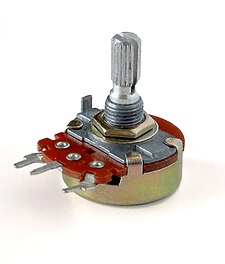
So I’m getting back to my mod project that I had to put off for my wedding and the start of my new job (oh life…), and I’ve been wondering what to do with the crossfader which I never use. I’ve dabbled with some mode settings with it and that’s how I intend to map it on my controller, but there have been times where I’ve accidentally knocked it and thrown my mix into a freefall.
So my thought is to replace the crossfader with a potentiometer with three detents or three-position toggle switch that sends three midi messages:
Am I going about this correctly? The ideal solution would be the toggle switch–it would give me a clear indicator of which mode I’m in. I know that most three-position toggle switches are on-off-on momentary digital switches but I figured I’d ask anyway.
You should look into a rotary switch. They come as 3 to 8 pole switches and will work really well for what you want to do. But I’m not sure how you would go changing the crossfaders analogue signal to digital to make the switch work.
Hope it’s some food for thought.
Thanks for the input! I will look into it over the weekend.
So far, I found a three-way toggle switch which is an on-on-on switch but it has 12 terminals. That would be difficult to wire up to an analog input for a crossfader.
I am looking into this again and somebody seems to have done some of the legwork for me albeit for a different application…
So if I use this SPDT switch
source
and wire it to an analog input, ideally I’d have 0v, 2.5v, and 5v at each position of the switch which means I will get midi cc 0, 64, and 127. If mapped correctly this can be pretty useful.
Let’s say I map it for headphone cue selection… at 0 deck A is in cue, at 127 deck B is in cue, and at 64 both are off. That’s kind of exciting to me
If anyone cares to help and can let me know how close I am on this I would apreciate it!
for as far as i know most pots have three inputs. how would your wiring look like exactly?
from what i understood you’d rather get 0 - 0 - 127 wich is not that helpful…
try it out, and report!
maybe you would want to use different resistors for the different switch positions to emulate different fader positions. for a 10kOhm fader those would be 10KOhm for 127, 5KOhm for 64, and none for 0.
give it a shot, resistors are a cheapo!
edit: oops, saw the wiring sceme further down the threat in your link…
Just swap it for a rotary potentiometer, or if bumping it is really that big of a problem (pick your knuckles up, you gorilla!! ;P) then put some tape over it. The way a switch works is completely different from the way a pot works, you will not be able to simply switch one for the other.
The pin on the IC that linear and rotary potentiometers are connected to are designed for analogue input. Without the datasheets for the individual components, I don’t believe there’s any way to tell if it will function properly and safely with a switch.
Never mind the fact that you would have to reprogram the firmware to follow the change of input…
No worries. I’m trying to build a custom controller, so I’m learning all this stuff right now, myself.
I should probably point out that you probably can’t just switch the fader with any ole rotary pot and expect it to work for a couple reasons…
First; what exactly are you trying to change the fader on? A digital or an analog device?
If it’s an analog device, you need to get a rotary fader, because a true crossfader essentially is two opposing pots in one device - when you turn one down, the other one is going up. See if you can find a repair manual for the device so you can get a rotary knob that has the same specs as the fader.
If it’s a digital device, you POSSIBLY can just use a simple pot - though again, check the spec’s. The problem with both of these is that cross-faders are often built to take a beating, so finding something with comparable specs may be expensive (especially buying a single unit instead of bulk, like a manufacturer can).
If I were you, I would simply consider putting some rubber, or anything that can increase friction, on the underside of the knob so that it takes even just a little more force to move.
It’s a midi device, not an analog mixer. Maybe I should have pointed that out in the OP!
It’s an X-Session Pro. I use it as my “party” controller (easy to bring along, not too bummed if it got jacked). The crossfader was used as a mode selector because I didn’t need it for its intended use.
So I wanted to rip out the crossfader and wire up a three-position switch. As far as I can tell, it’s just a linear potentiometer with some give to it so it’s not like there’s some crazy technology behind it.
I’m intrigued by derschaich’s post… If I got 2.5v and 5v out of each switch position by using resistors, I wonder if that would emulate the power output of a potentiometer at half and full turns.